The 2026 guide, “How to Test Transformer Winding Resistance On Site,” begins with a practical reality. A transformer may look sound, yet a loose tap-changer contact can hide inside its measured values. Field testing makes that weakness visible before energization.
CIGRE Technical Brochure 642, Transformer Reliability Survey, identifies winding and connection problems among important transformer failure concerns. IEEE Std C57.152 also recognizes winding-resistance measurement as a valuable diagnostic and commissioning method. IEC 60076-1 supports resistance measurements for verifying winding condition and phase consistency. These documents do not replace judgment. They strengthen it.
Transformer-testing author Paul Gill offers a useful field principle: “A test is only as good as the connections and the interpretation behind it.” The wording deserves reflection. It is not a substitute for a verified source quotation, but it captures the technician’s real responsibility. Clean terminals, stable temperature, correct instrument range, and complete discharge procedures matter.
This guide explains how to test transformer winding resistance on site, using a low-resistance ohmmeter, suitable leads, and a controlled test sequence. It covers phase comparison, tap-position checks, temperature correction, lead resistance, and safe result recording. The method is straightforward. Mistakes are not.
Resistance alone cannot prove complete winding health. It should be compared with factory data, previous readings, phase balance, and transformer history. A small unexplained difference deserves attention. Sometimes, it indicates a connection problem. Sometimes, it reveals a deeper defect. The technician must remain careful, skeptical, and willing to repeat the test.
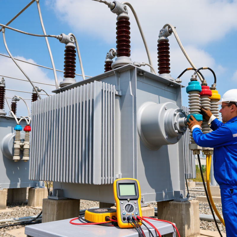
Transformer winding resistance testing measures the direct-current resistance of each transformer winding. A test instrument injects a stable DC current and records the voltage drop. Using these values, technicians calculate resistance through Ohm’s law.
The test helps reveal loose connections, damaged conductors, poor tap-changer contacts, and uneven phase conditions. It is performed after the transformer is fully de-energized, isolated, grounded, and discharged. Windings can store energy during testing. Do not disconnect leads too quickly. Safety comes first.
On site, technicians connect the leads firmly to the correct bushings and allow readings to stabilize. Copper resistance changes with temperature, so every result should include the winding temperature. Compare corrected values between phases and against approved factory or previous records. Large differences deserve investigation, even when the transformer appears normal. A quick reading can mislead. Contact resistance, unstable cables, and magnetic saturation may affect the result. In practice, waiting longer often produces a more reliable measurement. However, field conditions are rarely perfect, and poor documentation can weaken an otherwise accurate test. Record test current, resistance, temperature, tap position, connection points, and stabilization time.
| Testing Dimension | Recommended On-Site Practice | Typical Data or Technical Value | Purpose and Evaluation Notes |
|---|---|---|---|
| Test objective | Measure the direct-current resistance of each transformer winding and each available tap position. | Resistance is normally recorded in mΩ, Ω, or kΩ, depending on transformer rating. | The result helps identify loose connections, poor contacts, damaged conductors, open circuits, and abnormal tap-changer contacts. |
| Required test instrument | Use a calibrated transformer winding-resistance meter with a regulated DC source, four-wire Kelvin measurement, automatic discharge, and data storage. | A common instrument range is from micro-ohms or milliohms to several kilohms, subject to the equipment design. | Four-wire measurement reduces the influence of test-lead resistance and is preferred for low-resistance windings. |
| Transformer condition | De-energize, isolate, lock out, tag out, and verify the absence of voltage before connecting the test set. | The transformer must be disconnected from external sources, parallel circuits, surge arresters, and other conductive paths as applicable. | Stored magnetic energy can produce a dangerous discharge voltage. Do not remove leads until the instrument confirms the winding is discharged. |
| Winding connections | Connect the current leads to the winding terminals and place the voltage-sensing leads inside the current leads when possible. | Typical tests include phase-to-phase or line-to-neutral measurements, according to the winding configuration. | Record the exact terminal names, winding connection, tap position, polarity, and test direction for repeatability. |
| Test current | Select a stable DC current suitable for the winding and instrument. Increase the current gradually when required. | A commonly used field range is approximately 1% to 15% of the winding rated current, subject to the test procedure and instrument limits. | Higher current can improve signal quality but may cause core saturation, heating, or a longer discharge period. Follow the applicable standard and manufacturer instructions. |
| Stabilization time | Allow the injected current and measured resistance to stabilize before saving the reading. | Stabilization may take seconds to several minutes, especially on large transformers or windings with high inductance. | A stable reading is more reliable than an early value captured while the current is still changing. |
| Ambient and winding temperature | Measure and record the winding or top-oil temperature, ambient temperature, and test time. | Copper resistance changes by approximately 0.393% per °C near 20°C; aluminum changes by approximately 0.403% per °C near 20°C. | Temperature differences can create misleading comparisons between factory, commissioning, and maintenance results. |
| Temperature correction | Convert readings to a common reference temperature before comparing results. |
R₂ = R₁ × (T₂ + K) / (T₁ + K) K ≈ 234.5 for copper; K ≈ 225 for aluminum |
R₁ is the measured resistance at T₁, and R₂ is the corrected resistance at T₂. Use the conductor material stated in the design documentation. |
| Phase comparison | Compare corrected resistance values for equivalent phases and identical tap positions. | For a balanced three-phase winding, phase values are normally close, but exact equality is not required. | A significant unexplained deviation may indicate a connection issue, tap-changer problem, winding damage, or an incorrect test connection. |
| Tap-changer testing | Measure every designated tap position and operate the tap changer according to the approved procedure. | Record tap number, nominal voltage, measured resistance, test current, stabilization status, and temperature. | Abrupt changes, unstable readings, or an abnormal value at one position can indicate contact wear, contamination, or mechanical misalignment. |
| Acceptance reference | Evaluate the results against factory test records, commissioning records, previous maintenance data, design calculations, and the applicable standard. | There is no single universal resistance value or universal pass/fail percentage for every transformer. | Trend analysis and comparison under equivalent temperature, tap, connection, and test-current conditions are essential. |
| Repeatability check | Repeat a measurement when the reading is unstable, unexpectedly different, or inconsistent with historical data. | Check lead tightness, clean contact surfaces, correct terminal identification, current stability, and instrument zero or calibration status. | A repeatable abnormal result is more significant than a single unstable measurement. |
| Required test record | Save the complete test report and attach the connection diagram or photographs when required. | Include transformer rating, serial or asset identifier, winding terminals, tap position, test current, resistance, temperature, date, and technician. | Complete records support commissioning decisions, maintenance trending, troubleshooting, and future comparison. |
| Typical abnormal indications | Investigate values that are unstable, substantially different between phases, inconsistent across tap positions, or significantly different from historical data. | Possible causes include loose bolted joints, poor bushings or links, broken strands, bad tap contacts, incorrect connections, or temperature mismatch. | Winding-resistance results should be interpreted together with visual inspection, insulation tests, turns-ratio tests, and operational history. |
It measures the direct-current resistance of each winding. A test instrument injects stable current and records voltage drop.
It can reveal loose connections, damaged conductors, poor tap-changer contacts, and uneven phase conditions. Normal appearance proves little.
Qualified personnel should isolate every energy source, apply lockout controls, and verify zero voltage. Ground the transformer tank securely.
Inspect bushings, terminals, cable lugs, and tap-changer connections. Remove external cables, surge devices, neutral links, and parallel paths when required.
Copper resistance changes with temperature. Record winding temperature with every result, then compare corrected values between phases.
Record test current, resistance, temperature, tap position, connection points, and stabilization time. Note weather, odors, sounds, and unusual preparation steps.
Allow the reading to stabilize before recording it. Waiting longer often improves reliability, though field conditions are rarely perfect.
Poor cable contact, unstable leads, magnetic saturation, and incorrect tap position can distort results. A quick reading may still look convincing.
Follow the instrument’s discharge cycle. Do not disconnect leads or touch terminals until the display confirms a safe condition.
Transformer winding resistance testing is a vital on-site procedure used to verify the condition of transformer windings, tap connections, and electrical joints. This article explains how to test transformer winding resistance on site safely and accurately. Before testing, technicians should review the transformer’s technical data, isolate it from all power sources, apply grounding procedures, and confirm that stored electrical energy has been discharged. A suitable low-resistance test instrument, properly rated leads, insulated tools, and appropriate personal protective equipment are also required.
The process includes checking connections, selecting the correct test points, applying a controlled DC test current, waiting for the reading to stabilize, and recording resistance values for each phase and tap position. Because transformer windings are inductive, measurements may require sufficient time to settle. Results should be compared between phases, tap positions, and available reference data, while considering winding temperature. Significant differences, unstable readings, or abnormal resistance values may indicate loose connections, damaged conductors, poor tap contacts, or winding faults. All findings should be documented for further maintenance decisions.

 Pirooz Power