2026 Top Amorphous Alloy Transformer How It Cuts No Load Losses?

Time:2026-09-09 Author:Isabella
0%

As electricity demand rises in data centers, factories, and urban networks, transformer efficiency is becoming a measurable operating priority. The U.S. Department of Energy’s transformer efficiency analysis reports that amorphous-core designs can reduce no-load losses by approximately 60–70% compared with conventional grain-oriented silicon-steel transformers, depending on rating and design. These savings occur continuously, even when the transformer supplies little or no load.

So, how does an amorphous alloy transformer reduce no load losses?

Its core uses rapidly quenched metal with a disordered atomic structure. This structure lowers hysteresis loss during repeated magnetization. The alloy also supports thinner core sections, which can reduce eddy-current losses. Picture a substation transformer energized overnight, humming lightly while production stops. Its core still consumes power, but an amorphous design can waste substantially less energy during those quiet hours.

The International Energy Agency has repeatedly identified efficient grids and reduced network losses as important tools for managing electricity demand and emissions. IEC 60076 testing principles provide the framework for verifying transformer losses, temperature rise, and performance under controlled conditions. Yet laboratory results are not the whole story. Actual savings depend on voltage regulation, harmonic content, maintenance, and yearly energization time.

The answer is not perfectly simple. An amorphous transformer may cost more initially, and installation conditions can affect its real return. Still, when no-load operation lasts for thousands of hours annually, the avoided losses can become financially meaningful. This 2026 guide examines the evidence, practical design factors, and limitations behind that claim.
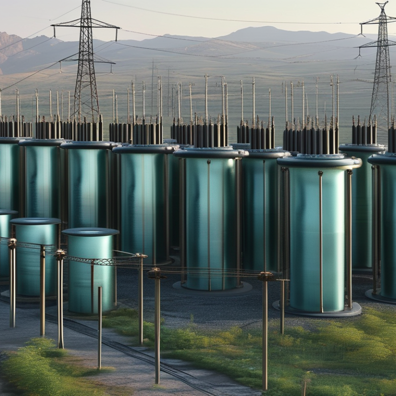
2026 Top Amorphous Alloy Transformer How It Cuts No Load Losses?

Amorphous Alloy Transformers: Structure, Materials, and Core Design

2026 Top Amorphous Alloy Transformer: How It Cuts No-Load Losses?

Amorphous alloy transformers use a wound core made from ultra-thin metallic ribbons. These ribbons cool rapidly during production, creating a disordered atomic structure. Unlike conventional steel, the material needs less energy to reverse its magnetic direction. That difference reduces hysteresis loss when the transformer remains energized without a load. Small savings continue every hour.

Core geometry matters as much as the alloy. A continuous wound core can reduce air gaps and magnetic leakage. Carefully shaped joints also limit local flux concentration. The primary and secondary windings surround the core with controlled spacing, insulation, and cooling paths. Designers must keep the core clamping pressure stable. Excessive pressure can distort the ribbon and increase losses.

In commissioning work, no-load measurements should be checked against factory data and temperature conditions. A quiet transformer is not automatically an efficient one. Technicians should inspect vibration, winding alignment, grounding, and connections. Amorphous ribbon is thin and sensitive to rough handling. One practical weakness remains: repairs can be more demanding than repairs on traditional laminated cores. I have also seen promising designs underperform when joints were poorly assembled. Better material alone cannot correct careless core construction.

2026 Top Amorphous Alloy Transformer: How It Cuts No-Load Losses

Amorphous alloy cores reduce no-load losses because their thin, disordered atomic structure produces lower hysteresis and eddy-current losses than conventional grain-oriented electrical steel. The values below represent typical 50 Hz core-loss densities used for comparative transformer design.

Key insight: At a representative 50 Hz operating point, amorphous alloy core material can reduce core-loss density by approximately 79% compared with conventional grain-oriented electrical steel. Actual transformer no-load loss also depends on core mass, flux density, joints, clamping, and manufacturing tolerances.

How Amorphous Metal Cores Reduce No-Load Energy Losses

Amorphous metal cores reduce no-load energy losses through their unusual atomic structure. Unlike conventional crystalline steel, the metal cools into a disordered form. This structure lowers magnetic hysteresis during repeated energizing. The core also uses extremely thin ribbons, often less than a tenth of a millimeter thick. Thin layers restrict circulating eddy currents. Less wasted current means less heat inside an energized transformer.

The difference appears even when the transformer supplies no load. It remains magnetized day and night, quietly consuming electricity. In a distribution cabinet, that background demand can continue for thousands of hours each year. Field measurements usually compare no-load watts at rated voltage and frequency. Temperature, waveform distortion, and core clamping can affect the reading. Measurement discipline matters.

The savings are not magic. Poor assembly, damaged ribbons, or unsuitable operating voltage can reduce performance. Designers must also consider sound levels, short-circuit strength, physical size, and purchase cost. An amorphous core may need careful handling because its ribbons are thinner and more fragile. That trade-off deserves honest review.

A transformer with lower measured losses may still perform poorly if installation conditions differ from laboratory tests. Engineers should record baseline consumption, verify operating voltage, and inspect readings after commissioning. Small errors can become expensive across many continuously energized units.

Key Factors Affecting Transformer No-Load Performance in 2026

2026 Top Amorphous Alloy Transformer: How It Cuts No-Load Losses

In 2026, no-load performance depends heavily on core design and manufacturing discipline. An amorphous alloy core uses extremely thin, glass-like metal strips. Their low hysteresis reduces energy wasted during continuous magnetization. The material also limits eddy currents inside the core. That matters when the transformer remains energized for long periods.

Core thickness is only one factor. Engineers must control flux density, operating frequency, and voltage waveform. Excessive flux pushes the core toward saturation. Noisy or distorted voltage can increase losses, even when rated voltage appears normal. Precise strip cutting and careful joint construction also affect magnetic resistance. Small gaps may create local heating and additional excitation loss. The calculation is not always enough.

Stress during winding and clamping can damage the core’s magnetic behavior. Proper annealing helps restore its performance after processing. Temperature changes also influence resistance, insulation condition, and measurement accuracy. Field testing should compare factory results with readings under actual load conditions. Keep the test room stable. A few degrees can alter results. I have seen specifications look excellent, yet installation details weakened real performance. Maintenance teams should inspect vibration, connections, cooling airflow, and voltage stability. These practical checks often reveal losses that laboratory data cannot fully explain.

Comparing Amorphous and Silicon Steel Transformer Technologies

In 2026, transformer buyers are comparing amorphous alloy cores with grain-oriented silicon steel. The key difference appears when the transformer is energized but lightly loaded. The U.S. Department of Energy’s 2016 Technical Support Document reports that amorphous designs can reduce no-load losses by roughly 60–70%. A 1,000 kVA transformer may hum through the night while supplying only lighting and controls. That idle energy is consumed continuously.

Silicon steel remains strong under load, widely understood, and easier to source in many markets. Its performance can also be competitive when loading stays high. Amorphous alloy usually wins at low load because its thin, disordered metal structure needs less magnetizing energy. However, core joints, manufacturing tolerances, and higher initial costs can reduce the expected advantage. The comparison is not perfectly clean.

The European Commission’s Ecodesign Regulation 548/2014 sets transformer loss limits, including no-load losses. IEC 60076 testing procedures support consistent verification under controlled conditions. Field commissioning teams should record no-load watts, ambient temperature, tap position, and actual load profiles. A spreadsheet based only on peak demand may misjudge payback. That mistake is common. Amorphous cores can also be more sensitive to mechanical damage, so installation discipline matters. The best choice depends on annual energized hours, tariff structure, footprint, and service capability. Even strong data needs site validation.

Applications, Benefits, and Selection Criteria for Amorphous Transformers

2026 Top Amorphous Alloy Transformer: How It Cuts No-Load Losses?

Applications, Benefits, and Selection Criteria for Amorphous Transformers

Amorphous alloy transformers use a rapidly quenched metal core with irregular atomic structure. This structure reduces magnetic hysteresis and eddy-current losses. The U.S. Department of Energy’s Distribution Transformer Energy Conservation Standards Technical Support Document reports potential no-load loss reductions of roughly 60–70% versus comparable silicon-steel designs. That difference matters because the core remains energized all day. A 500 kVA unit in a commercial building may consume energy even at midnight, when its load is nearly zero.

These transformers fit hospitals, data centers, renewable-energy sites, and lightly loaded rural feeders. They are especially useful where annual operating hours are high. Lower standby losses can reduce lifetime electricity costs and support grid-efficiency targets discussed in the IEA Electricity 2024 analysis. Benefits also include lower core heating and reduced environmental impact over long service periods. However, the purchase price may be higher. Payback depends on electricity tariffs, load patterns, installation space, and expected service life.

Selection requires more than comparing nameplate ratings. Check no-load loss, load loss, sound level, impedance, temperature rise, insulation system, and short-circuit strength. Ask for tested values under applicable IEC or IEEE standards. Site conditions matter. Harmonic currents from inverters can increase heating. In practice, buyers sometimes overestimate savings by using ideal load profiles. Real measurements are better. A year of feeder data can reveal whether the premium is justified.

2026 Top Amorphous Alloy Transformer: How It Cuts No-Load Losses — Applications, Benefits, and Selection Criteria
Data Dimension Amorphous Alloy Transformer Conventional Grain-Oriented Silicon-Steel Transformer Practical Significance
How Amorphous Metal Cuts No-Load Losses
Core material Rapidly quenched iron-based amorphous alloy with a non-crystalline atomic structure Crystalline grain-oriented electrical steel The amorphous structure reduces magnetic domain-wall movement and hysteresis loss.
Typical no-load loss reduction Approximately 60–80% lower Reference level Actual savings depend on transformer rating, design, flux density, loading profile, and applicable efficiency standard.
No-load loss mechanism Lower hysteresis loss and generally lower eddy-current loss at distribution-transformer operating frequencies Higher magnetic core loss under continuous energization No-load loss occurs whenever the transformer is energized, even when it supplies little or no load.
Core operating flux density Commonly designed at a lower flux density than many silicon-steel cores; the exact value is manufacturer- and design-specific Typically designed at a higher flux density, subject to material grade and noise requirements Lower flux density can reduce core loss but may increase core size and material volume.
Annual energy-saving potential Highest where the transformer remains energized for long periods at low or variable load Lower under the same operating schedule Annual savings should be calculated from the no-load-loss difference multiplied by energized hours.
Technical and Operating Characteristics
Typical frequency 50 or 60 Hz distribution applications 50 or 60 Hz distribution applications Both technologies require a design matched to the system frequency.
Common distribution ratings Often available from small service transformers through medium-voltage distribution ratings; commonly evaluated in the 25–2,500 kVA range Available across a broad range of distribution and power ratings Availability should be confirmed for the required voltage, impedance, enclosure, and installation method.
Typical voltage class Low-voltage and medium-voltage distribution systems, commonly up to approximately 36 kV class depending on design Low-voltage and medium-voltage distribution systems Specify primary and secondary voltage, insulation level, tap range, and neutral arrangement.
Load loss Determined mainly by winding resistance, conductor design, stray losses, and operating temperature Determined mainly by winding resistance, conductor design, stray losses, and operating temperature Amorphous technology primarily targets core loss; it does not automatically minimize load loss.
Audible sound Can be comparable to or somewhat higher than an optimized silicon-steel design if flux density, clamping, and enclosure are not carefully controlled Often easier to optimize for low acoustic noise because of established core construction methods For urban or indoor projects, request a guaranteed sound level and test method.
Mechanical robustness Thin amorphous ribbons require careful core handling, clamping, transport, and short-circuit design Generally more tolerant of handling and mechanical stress Installation quality and short-circuit withstand requirements should be reviewed before selection.
Applications and Benefits
Utility distribution Feeder and substation distribution transformers that remain energized continuously Conventional distribution service Reduced standby losses can improve system efficiency across large installed fleets.
Commercial buildings Office buildings, retail centers, hospitals, hotels, and campuses with fluctuating daily loads Suitable where purchase cost or space constraints dominate Energy savings are most valuable when equipment operates 24 hours per day.
Renewable-energy facilities Solar and wind collection systems, auxiliary transformers, and plant distribution networks Also suitable when compatible with the converter and grid interface Evaluate harmonics, load cycling, inverter compatibility, and required thermal margin.
Data centers and critical facilities Continuous-service distribution where efficiency and reduced lifetime energy consumption are priorities May be selected for established supply chains or specific footprint requirements Redundancy, inrush behavior, noise, thermal performance, and maintenance access remain essential.
Industrial plants Best suited to auxiliary and distribution loads with long energized periods and moderate average loading Suitable for high-duty-cycle and demanding mechanical environments Check harmonic current, motor starting, short-circuit duty, and enclosure conditions.
Environmental benefit Lower operating losses can reduce electricity consumption and associated indirect emissions Environmental performance depends on operating efficiency and grid electricity mix Use measured loss data and actual load profiles for a credible life-cycle comparison.
Selection Criteria
Rated power Select the kVA rating from maximum demand, expected growth, motor starting, duty cycle, and required spare capacity. Oversizing can increase purchase cost and physical size, while undersizing can cause overheating and reduced service life.
Primary and secondary voltage Specify nominal voltage, highest system voltage, phase arrangement, frequency, neutral, and tap requirements. Voltage compatibility must be verified with the utility or facility electrical design.
Efficiency and loss data Request guaranteed no-load loss, load loss, impedance, tolerances, and test conditions at the required temperature. Do not compare quotations using only a general efficiency percentage.
Load profile Use annual energized hours, average load factor, peak demand, seasonal variation, and standby periods. Amorphous cores generally provide the strongest economic advantage at low or variable average loading.
Total cost of ownership Compare purchase price, installation, energy losses, maintenance, expected service life, and disposal or recycling costs. A higher initial price can be justified when energy savings recover the premium within the project’s financial period.
Installation constraints Check dimensions, weight, ventilation, clearances, lifting points, fire protection, enclosure rating, and indoor or outdoor location. Amorphous designs may require more space or weight for the same rating because of lower design flux density.
Power-quality requirements Review harmonic content, non-linear loads, voltage distortion, inrush current, unbalance, and frequent energization. Specify suitable derating or design provisions where the transformer supplies rectifiers, variable-speed drives, or data-processing loads.
Compliance and testing Require compliance with the applicable national and international transformer standards, routine tests, temperature-rise limits, dielectric tests, and loss measurements. Acceptance criteria should be written into the procurement specification before ordering.
Warranty and service support Confirm warranty duration, spare-part availability, inspection procedures, repair capability, and technical documentation. Long-term support is important because core handling and repair procedures differ from conventional steel-core units.
Quick Decision Guide
Choose amorphous alloy when The transformer will remain energized for many hours, average loading is low or variable, energy efficiency is prioritized, and adequate installation space is available. Strong candidate
Review alternatives when The installation has severe space or weight restrictions, unusually high short-circuit stress, demanding acoustic limits, or a very short operating schedule. Detailed comparison required
Recommended evaluation method Compare guaranteed losses using the same rating, voltage, impedance, temperature reference, test standard, load profile, and electricity price. Use life-cycle cost

FAQS

: What is an amorphous alloy transformer?

: It uses ultra-thin metallic ribbons with a disordered atomic structure. The wound core remains energized during operation.

How does it reduce no-load energy loss?

The amorphous structure needs less energy for magnetic reversal. Thin ribbons also restrict circulating eddy currents. Less wasted energy becomes heat.

What happens when the transformer has almost no load?

The core still consumes electricity while magnetized. This background demand continues overnight and during quiet periods. Small savings accumulate.

Where are these transformers most useful?

They suit hospitals, data centers, renewable-energy facilities, and lightly loaded feeders. They work best with many energized hours. Nighttime savings can matter.

Can the savings be guaranteed?

No. Site conditions affect actual results. Voltage, frequency, temperature, harmonics, and assembly quality change measurements. Laboratory estimates may look too optimistic.

What should buyers compare before selecting one?

Check no-load loss, load loss, sound level, impedance, and temperature rise. Also review insulation, cooling, and short-circuit strength. The nameplate is not enough.

How should technicians verify performance after installation?

Measure no-load watts at rated voltage and frequency. Record temperature and waveform conditions. Inspect grounding, connections, vibration, and winding alignment.

What are the main disadvantages?

The initial price may be higher. The ribbons are thin and fragile. Repairs can be more demanding than traditional core repairs.

Can core design affect efficiency?

Yes. Continuous winding, accurate joints, and stable clamping reduce unwanted magnetic effects. Excessive pressure may distort the ribbons. Better material cannot fix careless construction.

Conclusion

Amorphous alloy transformers use a magnetic core made from rapidly cooled, non-crystalline metal ribbons. This unique structure creates low magnetic hysteresis and reduces eddy-current formation during operation. The key question is: how does an amorphous alloy transformer reduce no load losses? Even when no electricity is being delivered to a load, the core remains energized. Because amorphous metal requires less energy to magnetize and demagnetize, the transformer consumes significantly less standby power than many conventional silicon steel designs.

In 2026, no-load performance depends on core material, ribbon thickness, joint design, flux density, manufacturing precision, insulation, cooling, and operating voltage stability. Compared with silicon steel transformers, amorphous models generally offer lower continuous energy loss, although their cores may require more careful handling and optimized construction. They are well suited to distribution networks, renewable energy systems, commercial buildings, and other applications where equipment remains energized for long periods. Selection should consider load profile, efficiency targets, installation conditions, lifecycle energy savings, maintenance requirements, and total ownership cost.

Isabella

Isabella

Isabella is a dedicated marketing professional with a sharp focus on driving brand growth and engagement through strategic content creation. With an extensive background in digital marketing, she combines her passion for storytelling with her keen understanding of industry trends to deliver......