What Is a Dry Type Isolation Transformer and How to Ground?

Time:2026-09-19 Author:Liam
0%

A dry type isolation transformer separates one electrical circuit from another through magnetic coupling. It does not make an installation automatically safe. Inside the quiet enclosure, windings, terminals, and metal parts still require careful bonding. A loose grounding connection can leave the cabinet energized during a fault. That danger may remain invisible until someone touches it.

This guide explains how to ground a dry type isolation transformer safely, using practical inspection steps and accepted electrical principles. Mike Holt, a respected electrical educator, states, “The purpose of grounding is to provide a low-impedance path for fault current.” That path should connect exposed metal parts back to the source grounding point. The neutral point may need bonding, or it may need isolation, depending on the transformer’s system configuration. Never assume.

Start with the manufacturer’s wiring diagram. Confirm the primary and secondary terminals. Identify the grounding electrode conductor, equipment grounding conductor, bonding jumper, and any separately derived system connection. De-energize the supply, lock it out, and verify zero voltage with a properly rated meter. Inspect the green or bare conductor for secure lugs, clean metal contact, and suitable sizing. Check continuity before energizing. Then test the installation under controlled conditions.

Small details matter.

A painted cabinet surface may interrupt bonding. An undersized conductor may fail during a fault. I have seen diagrams that looked clear but hid confusing neutral symbols. That is why a qualified electrician should review the work, especially in commercial or industrial settings. Local requirements and transformer instructions can differ. Safe grounding is not a shortcut. It is a documented process, verified connection by verified connection.
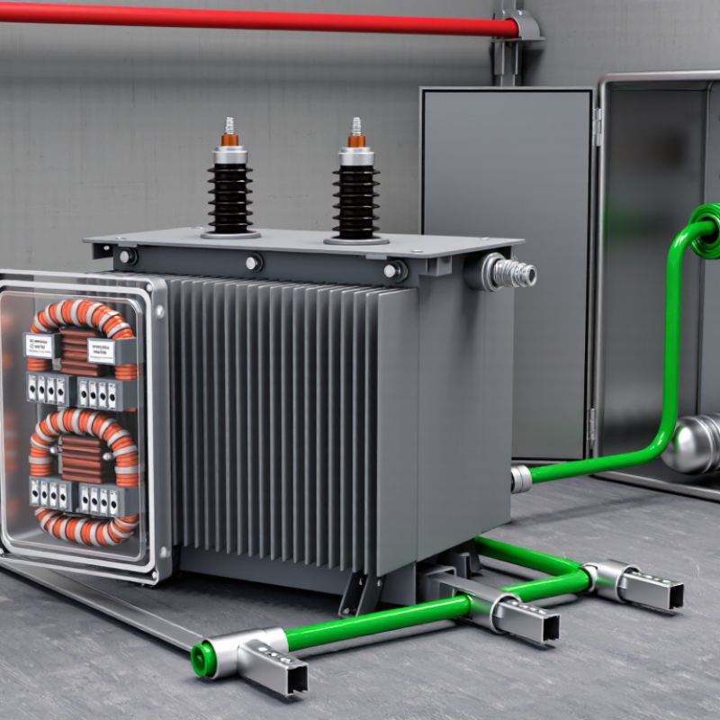
What Is a Dry Type Isolation Transformer and How to Ground?

What Is a Dry-Type Isolation Transformer?

A dry-type isolation transformer transfers electrical energy through magnetic coupling without a conductive connection between its primary and secondary windings. “Dry-type” means it uses air or solid insulation instead of oil or another liquid. This reduces leak concerns and suits indoor electrical rooms, workshops, medical areas, and control systems. The core and windings are enclosed or ventilated, so heat must leave through air movement and the enclosure. That detail matters. A quiet transformer can still run too hot when ventilation is blocked.

The isolation barrier helps limit fault paths, electrical noise, and certain shock hazards. It does not make an installation automatically safe. The secondary voltage, load size, insulation class, and available fault current still require careful assessment. In the field, technicians check nameplate data, winding connections, terminal torque, and temperature rise before energizing. Small mistakes happen, especially when primary and secondary terminals look similar. Clear labeling is not optional.

Grounding needs a deliberate plan. The transformer enclosure and core are normally bonded to the protective grounding conductor. The secondary circuit may require one intentional bonding point, often at the transformer or first disconnect, depending on system design and local electrical rules. Multiple neutral-to-ground bonds can create unwanted current on metalwork. Grounding conductors should be sized, routed, and tested by a qualified electrician. A continuity test helps, but it does not replace insulation and polarity checks. Some installations need a different arrangement.

How Does a Dry-Type Isolation Transformer Work?

A dry-type isolation transformer transfers electrical energy through magnetic coupling, not a direct conductive connection. The input winding creates a changing magnetic field in the core. This field induces voltage in a separate output winding. Both sides share the same frequency, but their conductors remain electrically isolated.

That separation helps reduce some noise and limits fault-current paths. Voltage may stay equal, rise, or fall, depending on the winding ratio. The transformer uses air or solid insulation instead of insulating liquid. You may hear a soft hum from the core. A warm enclosure is normal, but excessive heat, buzzing, or a burning smell needs immediate inspection. The enclosure and core should connect to protective earth. The secondary grounding method depends on the installation design and local electrical requirements.

Tips: Have a qualified electrician verify the grounding arrangement before energizing the unit. Check continuity between the enclosure and grounding conductor with power disconnected. Do not assume a floating secondary is safer. In some systems, one secondary conductor is bonded to ground at a defined point. Multiple bonding points can create unwanted current paths. Labels and diagrams can be incomplete, so measure carefully. A voltage tester confirms presence, not a complete safety assessment.

How a Dry-Type Isolation Transformer Works

A dry-type isolation transformer transfers AC power through magnetic induction rather than a direct electrical connection. Its primary and secondary windings are separated by insulation, providing galvanic isolation while maintaining the selected voltage ratio. The example below shows an ideal 1:1 transformer supplied with 120 V RMS at 60 Hz.

Grounding Principle

  • Connect the transformer enclosure and core to the protective earth conductor.
  • For a separately derived secondary, bond the secondary neutral to protective earth at one designated point, where required by local electrical codes.
  • Do not create additional neutral-to-earth bonds downstream of the designated bonding point.
  • Use a qualified electrician and follow the applicable electrical standards for the installation.

What Are Its Main Components and Applications?

A dry-type isolation transformer transfers electrical power without a direct conductive connection between its windings. Its main components are a laminated steel core, primary winding, secondary winding, insulation, terminals, and a ventilated enclosure. The core guides magnetic flux, while insulation separates energized conductors from each other and from the enclosure. Many units also include an electrostatic shield, temperature sensors, and cooling channels.

These transformers serve hospitals, laboratories, control panels, renewable-energy systems, and sensitive electronic equipment. They can reduce unwanted electrical noise and limit fault-current paths. However, isolation does not automatically make a circuit safe. I have seen installations where operators assumed the secondary side needed no grounding. That assumption can create serious shock risks.

Grounding normally begins by bonding the metal enclosure and transformer core to protective earth. For a separately derived secondary system, a qualified electrician usually bonds one secondary conductor to ground at the designated source point. The exact arrangement depends on the voltage system, local electrical code, and equipment design. A shield, when installed, should connect to the grounding system without creating random parallel paths. Keep it deliberate.

Avoid multiple neutral-to-ground bonds. They can produce circulating current, nuisance trips, or unexpected touch voltage. Grounding conductors should be correctly sized, secured, and tested for continuity. A commissioning check should include insulation resistance, polarity, bonding, and fault protection. One detail is easy to miss: ventilation openings must remain clear, because heat weakens insulation over time. My own practical caution is simple—never copy a grounding diagram without checking the transformer’s nameplate and the site’s protection system.

How to Ground a Dry-Type Isolation Transformer Safely?

A dry-type isolation transformer separates circuits through magnetic coupling, not a direct conductive path. That separation reduces transferred noise, but it does not remove shock or fault hazards. Safe grounding starts by identifying the secondary as a separately derived system. IEEE Std 142 and NEC 250.30 explain this distinction and its bonding implications. The U.S. Bureau of Labor Statistics recorded 126 fatal occupational injuries involving electricity in 2022. Grounding is not paperwork.

Before work, qualified personnel should isolate, lock out, and verify zero voltage with a properly rated tester. Bond the transformer enclosure and accessible metal parts to the equipment grounding conductor. Follow the manufacturer’s instructions for internal core grounding. At the secondary source, place the system bonding jumper at the designated neutral point. Install the grounding electrode conductor according to local electrical requirements. Avoid downstream neutral-to-ground bonds unless the design specifically requires them. One extra bond can place normal current on metal paths. Use listed lugs, clean contact surfaces, and the specified torque. Check continuity, phase identification, and insulation condition before energizing. A low resistance reading alone does not prove a correct grounding system.

Tips: Photograph existing terminations, then compare them with the wiring diagram. Ask an independent electrician to review the single-line drawing. NFPA 70B supports documented inspection and maintenance testing, yet field conditions can change. Do not copy an older installation blindly; it may hide a neutral bond or an undersized conductor. That mistake is easy to miss.

What Is a Dry Type Isolation Transformer and How to Ground? - How to Ground a Dry-Type Isolation Transformer Safely?

Data Dimension Typical or Recommended Value Grounding Relevance Safe Practice
Transformer type Dry-type, two-winding isolation transformer The primary and secondary windings are electrically separated. Do not assume that the secondary neutral is grounded merely because the primary system is grounded.
Common voltage ratio 1:1 for electrical isolation; other ratios may be used for voltage conversion. A 1:1 ratio does not remove the need for protective grounding. Verify the nameplate primary and secondary voltage before wiring.
Operating frequency Usually 50 Hz or 60 Hz, as marked on the nameplate. Frequency mismatch can cause overheating, excessive current, or abnormal noise. Use the transformer only within its marked frequency and voltage ratings.
Primary-side grounding Connect the primary circuit protective earth to the transformer enclosure and core assembly where required. Provides a low-impedance fault-current path if primary insulation fails. Use the designated grounding terminal; do not rely on conduit, mounting hardware, or paint alone.
Secondary system status May be floating or intentionally grounded, depending on the system design and applicable electrical code. A floating secondary can reduce certain first-fault currents but requires suitable monitoring and protection. Never ground the secondary casually; follow the approved schematic and local code.
Secondary system bonding point For a grounded separately derived system, bond the designated secondary neutral point, commonly X0, at one location only. Creates a reference to earth and a fault-current return path. Install the system bonding jumper at the transformer or the approved first disconnecting means, not at multiple locations.
Secondary equipment grounding conductor Run with the secondary circuit conductors to downstream equipment. Maintains continuity of protective grounding throughout the secondary system. Connect it to equipment grounding terminals and metal enclosures; size it according to the governing code.
Neutral-to-ground connections Normally one intentional connection for a grounded secondary derived system. Additional downstream bonds can place normal neutral current on grounding paths. Remove downstream neutral-to-enclosure bonds unless specifically required by the system design.
Grounding electrode connection Connect the grounded secondary system to the grounding electrode system when required for a separately derived system. Stabilizes the system-to-earth voltage and supports fault protection. Use an appropriately sized grounding electrode conductor and connect it at the approved bonding point.
Insulation resistance check Test values must meet the manufacturer’s instructions and applicable standards; no universal pass value applies to every transformer. Detects moisture, damaged insulation, or unintended winding-to-ground connections. Disconnect sensitive electronics before testing with an insulation-resistance tester.
Continuity and polarity verification Verify conductor continuity, winding polarity, terminal identification, and grounding conductor continuity before energizing. Incorrect polarity or an open protective conductor can create dangerous touch voltage or circulating current. Use a calibrated meter and compare results with the wiring diagram and nameplate.
Enclosure and ventilation Keep ventilation openings clear and maintain the manufacturer’s required installation clearances. Overheating can degrade insulation and increase the risk of ground faults. Install in a dry, clean location and bond all accessible metal parts that are part of the enclosure.
Protection and disconnection Provide correctly rated primary and secondary overcurrent protection and an accessible disconnect where required. Grounding does not replace overcurrent protection or safe isolation procedures. De-energize, lock out, tag out, and verify absence of voltage before working on the transformer.
Final commissioning check Confirm voltage, phase relationship, grounding continuity, insulation condition, and protective-device operation. Confirms that the isolation and grounding arrangement performs as designed. Have installation and testing completed or verified by a qualified electrician in accordance with local regulations.
Safety note: The correct grounding method depends on the transformer’s wiring diagram, whether the secondary is treated as a separately derived system, and the electrical code applicable at the installation site. Work on energized equipment should be performed only by qualified electrical personnel.

What Safety Standards and Maintenance Practices Apply?

A dry type isolation transformer separates primary and secondary windings without using liquid insulation. Its construction reduces fire and leakage concerns, but it does not remove shock hazards. Grounding remains essential. The metal enclosure should connect to the protective grounding conductor with a secure, low-impedance bond. The secondary neutral should be grounded only when the engineered system design requires it. Never assume isolation means the output is automatically safe.

Safety work should follow applicable standards, such as IEC 60076-11 for dry type transformers. In North America, NFPA 70 provides requirements for grounding, bonding, overcurrent protection, and installation methods. Workplace electrical rules may also apply. Local codes can differ. A qualified person should verify clearances, fault-current ratings, conductor sizes, and grounding connections before energizing the transformer. Never improvise a neutral-to-ground connection.

Maintenance begins with a documented inspection schedule. After de-energizing and verifying zero voltage, inspect terminals for looseness, discoloration, corrosion, or cracked insulation. Use a calibrated torque tool when tightening connections. Check insulation resistance only with suitable test equipment and an approved procedure. Remove dust carefully, because accumulated dust can restrict cooling and encourage tracking. Listen for unusual humming. Thermal imaging can reveal a hot terminal before failure. Record load, temperature, test results, and corrective work. I have seen small loose connections create serious heat. That detail is easy to miss. Every installation deserves a fresh review.

FAQS

How does a dry-type isolation transformer transfer electrical energy?

The input winding creates a changing magnetic field. This field induces voltage in a separate output winding. No direct conductive connection exists. Both windings share the same frequency.

Does isolation always make the secondary circuit safe?

No. Isolation reduces some noise and limits certain fault-current paths. It does not remove shock hazards. Grounding and protection still matter. Never assume a floating secondary is safer.

Can the transformer output voltage change?

Yes. The output voltage depends on the winding ratio. It may remain equal, rise, or fall. Check the nameplate before energizing the unit.

What parts are found inside a dry-type isolation transformer?

Common parts include a laminated steel core, primary winding, secondary winding, insulation, terminals, and enclosure. Some units contain shields, temperature sensors, and cooling channels. The enclosure may feel warm.

Where are these transformers commonly used?

They support hospitals, laboratories, control panels, renewable-energy systems, and sensitive electronic equipment. They can reduce unwanted electrical noise. Their benefits depend on correct installation.

How should the transformer enclosure and core be grounded?

The metal enclosure and core should connect to protective earth. Grounding conductors must be correctly sized and secured. A qualified electrician should verify continuity with power disconnected.

How is the secondary grounding arrangement selected?

A separately derived secondary usually bonds one conductor at the designated source point. The exact method depends on voltage, equipment design, and local requirements. Avoid copying diagrams blindly.

What problems can multiple neutral-to-ground bonds cause?

Multiple bonds can create circulating current, nuisance trips, or unexpected touch voltage. Keep the bonding arrangement deliberate. This detail is easy to miss.

What warning signs require immediate inspection?

Excessive heat, loud buzzing, or a burning smell requires prompt inspection. A soft core hum can be normal. Keep ventilation openings clear. Heat gradually weakens insulation.

What checks should occur before energizing the transformer?

Check insulation resistance, polarity, bonding, continuity, and fault protection. A voltage tester only confirms voltage presence. It does not prove complete safety. I would not rely on it alone.

Conclusion

A dry-type isolation transformer transfers electrical energy between separate windings without using liquid insulation, creating galvanic isolation between the power source and the connected load. It is commonly used to reduce electrical noise, improve power quality, and protect sensitive equipment in industrial, commercial, medical, and control applications. Its main components typically include primary and secondary windings, a magnetic core, solid insulation, terminals, an enclosure, and cooling paths. During operation, alternating current produces a magnetic field in the core, which induces a corresponding voltage in the isolated secondary winding.

Understanding how to ground a dry type isolation transformer safely is essential for protecting people and equipment. The enclosure, core, and other exposed conductive parts should be bonded to a reliable protective grounding system in accordance with applicable electrical codes. The secondary system should be grounded only as required by its design and local regulations, with correct bonding and overcurrent protection. Installation and maintenance should be performed by qualified personnel, including inspection of connections, insulation, ventilation, temperature, dust buildup, and abnormal noise. Safety standards, documented testing, and scheduled servicing help ensure dependable operation.

Liam

Liam

Liam is a dedicated marketing professional with a profound expertise in the industry, where he excels at highlighting the unique advantages of our core products. With a keen understanding of market trends and consumer needs, Liam frequently updates our company’s professional blog, providing......