Oil-filled transformers support reliable power distribution, but their insulating oil can intensify a small electrical fault. When people ask, “what are the main causes of fires in oil filled transformers,” the answer usually involves several connected failures. Internal arcing, insulation breakdown, overheating, loose connections, and damaged bushings are common contributors. A minor defect may remain hidden until heat, pressure, and electrical stress combine.
A transformer can show warning signs before ignition. Technicians may notice a sharp burnt-oil smell, unusual humming, rising oil temperature, or darkened porcelain around a bushing. Oil leaks also matter. Low oil levels reduce insulation performance and cooling capacity. Moisture, aging paper insulation, poor maintenance, and excessive loading can accelerate deterioration. Faults in tap changers and cable terminations deserve close attention. Small details matter.
Fire investigations should rely on evidence, not assumptions. Engineers typically review protection records, dissolved gas analysis, infrared images, oil tests, inspection reports, and relay operations. Standards such as IEC 60076 and applicable fire-protection guidance can support a disciplined assessment. Yet the cause is not always obvious. Records may be incomplete, and several defects may exist together. That uncertainty requires humility.
This article examines the main ignition sources, warning indicators, and preventive controls for oil-filled transformer fires. It also considers containment, automatic protection, routine testing, and safe inspection practices. Understanding the sequence of failure can help operators reduce damage, protect nearby equipment, and improve emergency response. Prevention starts with evidence.
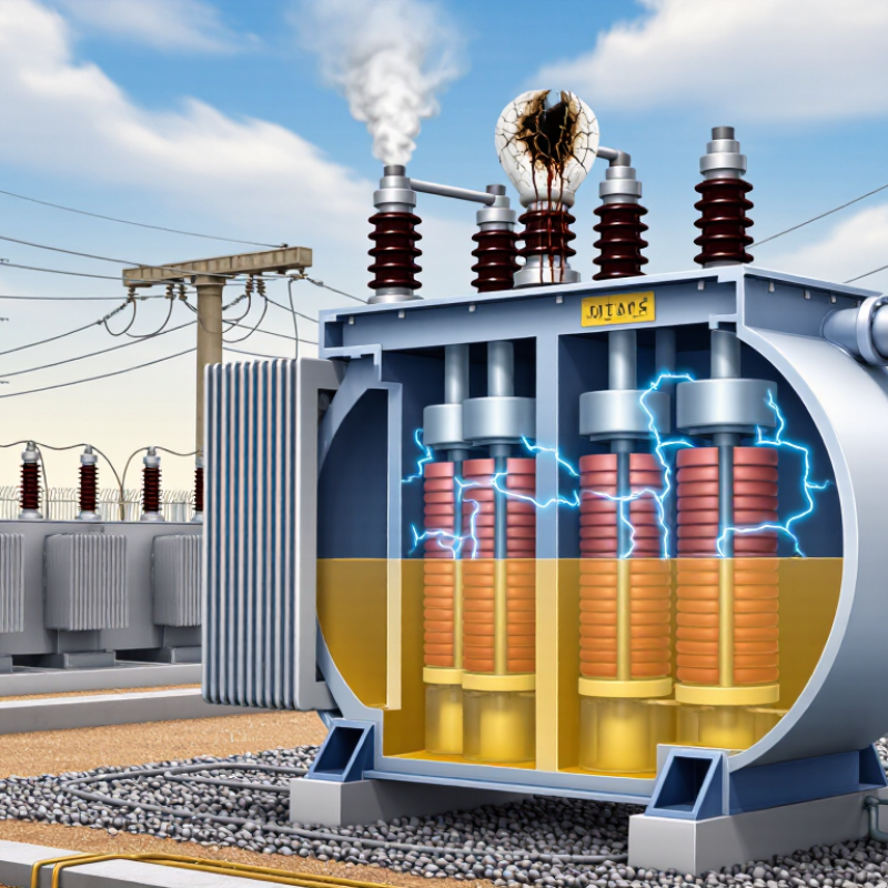
An oil-filled transformer needs three conditions to burn: heat, fuel, and oxygen. This is the fire triangle. Remove one side, and ignition becomes far less likely. Transformer oil and paper insulation provide the fuel. Oxygen usually enters through a conservator, breather, damaged seal, or tank rupture. The flame follows.
Heat often begins with an electrical fault. A short circuit, loose connection, overloaded winding, or failing bushing can create intense local temperatures. Arcing may puncture insulation and ignite oil vapour. Poor cooling makes the problem worse. Blocked radiators, low oil levels, and failed fans can raise operating temperatures for hours. Maintenance teams should check oil temperature, dissolved gases, connections, and protection records. Small warning signs matter.
The fuel side is not limited to oil. Aged cellulose insulation can char and release combustible gases. Contaminated or degraded oil may also reduce insulation strength. Oxygen becomes especially dangerous after a violent internal fault opens the tank. Pressure relief devices can limit damage, but they cannot correct every failure. A clean exterior can mislead inspectors. This is where judgment becomes difficult. It is easy to blame the oil, yet heat and oxygen often decide whether a fault becomes a fire. Regular thermographic inspections, oil testing, relay checks, and verified grounding can expose weaknesses before sparks meet air.
Oil-filled transformer fires often begin with heat, not flames. Overloading raises winding current and creates a localized hot spot inside the tank. The oil may still look normal while paper insulation quietly loses strength. IEEE C57.91 uses a practical rule: every 6°C increase in winding hot-spot temperature can approximately double the insulation aging rate. A transformer running 12°C hotter may age about four times faster, although actual results depend on moisture, oxygen, design, and operating history.
As insulation ages, it becomes brittle and less resistant to electrical stress. Faults can then produce arcing, rapid gas formation, and pressure inside the tank. Leaking oil, blocked cooling paths, loose connections, or failed fans can intensify the event. Field inspections should compare load current, ambient temperature, oil temperature, and hot-spot estimates. Do not rely on one gauge. A sensor can miss a small but dangerous internal hot spot. That assumption deserves review.
Tips: Record peak loads and temperature trends, not isolated readings. Inspect radiators, pumps, conservators, bushings, and oil levels during routine maintenance. Use alarms for abnormal temperature and pressure changes. Reduce loading when cooling equipment fails. Review protection settings with a qualified engineer. The 6°C rule is a warning tool, not a precise prediction of fire timing. Transformers are complicated, and real conditions rarely behave perfectly.
| Primary Cause | Typical Initiating Condition | How the Failure Develops | Common Warning Indicators | Fire or Explosion Pathway | Risk Level | Key Prevention and Detection Measures |
|---|---|---|---|---|---|---|
| Prolonged Overloading | Load current remains above the transformer’s rated value, especially during peak demand or emergency loading. | Higher current increases winding losses and conductor temperature. The resulting hot-spot temperature accelerates paper insulation deterioration and reduces mechanical strength. |
|
Degraded insulation can lead to turn-to-turn faults, arcing, rapid gas generation, oil rupture, and ignition of mineral oil vapor. | High | Monitor load, winding hot-spot temperature, and ambient temperature. Apply the thermal loading methods in IEEE C57.91 and maintain adequate cooling capacity. |
| Thermal Aging of Solid Insulation | Long-term operation at elevated winding hot-spot temperatures, even without a sudden overload. | Cellulosic insulation gradually loses degree of polymerization, becomes brittle, and loses tensile strength. Aging also reduces the insulation’s ability to withstand short-circuit forces. |
|
Weak insulation may fail during a fault or switching event, allowing internal arcing and rapid pressure rise. | High | Use thermal monitoring, oil laboratory testing, furans analysis where applicable, moisture control, and loading records. Investigate persistent hot-spot temperatures rather than relying only on average oil temperature. |
| IEEE C57.91’s 6°C Rule | Winding hot-spot temperature rises above the reference temperature used for normal insulation aging. | IEEE loading guidance commonly expresses the thermal aging relationship so that each 6°C increase in hot-spot temperature approximately doubles the relative aging rate over the applicable range. The rule is an approximation, not a universal failure-time guarantee. |
|
The rule does not directly ignite oil; it explains why excessive temperature can shorten insulation life and increase the probability of an internal fault that may ignite oil. | High | Calculate hot-spot temperature and per-unit aging rate using the latest applicable IEEE C57.91 methodology. Record duration, ambient temperature, and loading history for each thermal event. |
| Moisture Contamination | Water enters through deteriorated seals, breathing systems, maintenance activities, or wet insulation during manufacturing or repair. | Moisture lowers the dielectric strength of oil and paper, increases insulation losses, and can produce bubbles during high-temperature operation. |
|
Reduced dielectric strength increases the likelihood of partial discharge, flashover, and internal arcing, which can ignite oil or generate explosive gas. | High | Maintain sealed or properly vented conservators, inspect gaskets and breathers, test moisture and dielectric strength, and dry or reclaim insulation when necessary. |
| Internal Electrical Fault | Turn-to-turn fault, winding-to-ground fault, core fault, or insulation breakdown caused by aging, contamination, manufacturing defects, or mechanical damage. | Fault current creates intense localized heating and an electrical arc. The arc decomposes oil and generates gas and pressure in a very short time. |
|
Arc energy can ignite oil vapor, rupture the tank, and produce a transformer fire or pressure-driven oil release. | High | Use differential, sudden-pressure, overcurrent, and gas-operated protection. Verify relay coordination and inspect the transformer after any protection trip before re-energization. |
| Loose or High-Resistance Connections | Loose bolted joints, poor crimping, damaged leads, or degraded internal connections create localized resistance. | Localized I²R heating damages nearby insulation and may carbonize paper. The defect can progress into arcing or a connection failure. |
|
Hot connections can ignite nearby oil vapor or initiate an internal arc and tank rupture. | High | Perform torque verification during maintenance, thermographic inspections under load, winding-resistance tests, and inspection of bushings and cable terminations. |
| Cooling-System Failure | Failure of fans, pumps, radiators, control circuits, oil flow paths, or temperature sensors. | Heat cannot be removed effectively, so top-oil and winding hot-spot temperatures rise even at normal electrical loading. |
|
Thermal stress accelerates insulation aging and can cause an internal fault or oil leakage near hot surfaces. | High | Test automatic cooling stages, maintain fans and pumps, verify control power, clean radiators, and provide alarms for loss of cooling capacity. |
| Oil Leakage and Low Oil Level | Damaged gaskets, corroded tanks, cracked radiators, failed valves, or bushing leaks. | Oil loss reduces insulation clearance and cooling performance. Escaped oil may collect near energized components or spread beyond the transformer enclosure. |
|
Leaked mineral oil can burn when exposed to an arc, hot connection, electrical fault, or nearby external ignition source. | High | Repair leaks promptly, maintain oil-level alarms, use bunds or oil-containment systems, keep drainage paths clear, and inspect tanks and radiators for corrosion. |
| Bushing Failure | Moisture ingress, contamination, seal deterioration, thermal stress, or internal dielectric breakdown in a bushing. | Electrical stress concentrates within the bushing insulation. Failure may produce surface flashover, internal arcing, or a mechanical rupture. |
|
A failed bushing can create an external arc, ignite leaked oil, or transmit a fault into the transformer tank. | High | Perform bushing capacitance and power-factor tests, inspect seals and porcelain or composite surfaces, and use online monitoring where justified by criticality. |
| Lightning and Switching Surges | Overvoltage from lightning, switching operations, fault clearing, or inadequate surge protection. | Transient overvoltage stresses winding insulation and may cause partial discharge, puncture, or a flashover at a weak point. |
|
A punctured winding or bushing can produce an internal arc, rapid gas generation, and oil ignition. | Medium to High | Install and maintain correctly rated surge arresters, verify grounding and lead lengths, and coordinate insulation levels with the system design. |
| On-Load Tap-Changer Fault | Contact wear, inadequate oil condition, failed transition resistors, mechanical malfunction, or incorrect switching sequence. | Arcing and overheating occur in the tap-changer compartment. A failed diverter or selector mechanism can create sustained fault energy. |
|
Internal arcing can ignite tap-changer oil or transfer a severe fault to the main transformer tank, depending on construction. | High | Follow operation-count maintenance intervals, test transition components, analyze tap-changer oil separately where applicable, and verify mechanical interlocks. |
| External Fire or Nearby Heat Source | Fire from adjacent equipment, cable trenches, vegetation, oil storage, or construction activity reaches the transformer. | External heat weakens seals, raises oil temperature, damages bushings, and may cause pressure relief or tank failure. |
|
External flames heat the oil and tank; released or spilled oil can sustain and spread the fire. | Medium to High | Provide fire separation, oil containment, drainage, vegetation control, suitable detection and suppression systems, and an emergency response plan. |
| Improper Maintenance or Incorrect Re-Energization | Foreign objects, tools left inside, incorrect clearances, incomplete drying, wrong protection settings, or energization after an unresolved alarm. | Maintenance-related defects reduce insulation clearances or disable protective functions, allowing a small defect to become a high-energy fault. |
|
Reduced clearances or unavailable protection may allow arcing, oil ignition, pressure rupture, and delayed fault isolation. | High | Use documented work permits, foreign-material controls, independent inspection, electrical testing, protection verification, and formal pre-energization checklists. |
| Hydrogen or Combustible Gas Accumulation | Partial discharge, overheating, arcing, or oil degradation generates combustible gases inside the tank or conservator. | Gas accumulates and changes the pressure and composition of the transformer atmosphere. A subsequent arc or hot surface can ignite the mixture. |
|
Ignition of combustible gas can cause a rapid pressure event, oil expulsion, tank rupture, and fire escalation. | High | Investigate gas alarms immediately, use properly maintained gas and pressure protection, sample oil after abnormal events, and never re-energize without fault assessment. |
| Engineering note: The 6°C relationship in IEEE C57.91 is a thermal-aging approximation used for loading calculations. It describes relative insulation aging as winding hot-spot temperature changes; it does not by itself predict the exact time or probability of a transformer fire. Fire risk depends on insulation condition, oil volume, fault energy, protection speed, containment, and site-specific design. | ||||||
What Are the Main Causes of Oil Filled Transformer Fires?
Transformer oil can ignite when heat, oxygen, and an ignition source meet. The ASTM D92 flash point, often near 140°C for mineral insulating oil, marks when vapors can briefly ignite. It does not mean the oil will burn continuously at that temperature. A hot connection, electrical arc, or failed bushing may create a much hotter local zone. The liquid may appear calm while vapor near the tank surface catches fire. CIGRE Technical Brochure 537 identifies internal faults, bushing failures, and oil leakage as recurring transformer fire pathways. That evidence makes the flash point a warning boundary, not a safe operating limit.
Internal arcing can rapidly decompose oil and produce flammable gases. A ruptured bushing may spray heated oil across nearby steelwork. Poor sealing can also place oil beside energized components. IEEE 979 stresses separation, fire barriers, drainage, and suppression planning for substation risks. Yet temperature monitoring alone can miss a short thermal event. This is an uncomfortable gap. A 140°C alarm may react too late when an arc has already started.
Tips: Trend top-oil and winding-hot-spot temperatures together. Inspect bushings, gaskets, breathers, and cable connections during each scheduled outage. Keep leaked oil away from ignition sources and drainage paths. Test protection systems, not just the transformer. ASTM D92 results also vary with sampling and test conditions, so treat the reported flash point as laboratory guidance, not an absolute field threshold.
What Are the Main Causes of Oil Filled Transformer Fires?
Internal arcing is one of the most dangerous precursors to an oil-filled transformer fire. It may begin between winding layers, across a damaged bushing, or near a loose connection. The arc rapidly decomposes insulating oil and paper. IEEE C57.104 identifies acetylene as a key indicator of high-energy electrical discharge. Hydrogen can also rise sharply. Methane and ethane usually suggest thermal oil decomposition, while carbon monoxide and carbon dioxide point toward paper insulation involvement.
CIGRE Technical Brochure 642 analyzed 964 transformer failures reported between 1996 and 2010. Its findings placed winding failures, bushings, and tap changers among important failure areas. These defects can create heat, gas, pressure, and eventually an oil-fed fire. A sudden acetylene increase deserves urgent attention, especially when hydrogen also climbs between samples. Yet gas analysis is not a fire prediction tool. A clean-looking result can still mislead. Sampling errors, dissolved-gas saturation, and changing load conditions require careful review.
Tips: Compare gas trends, not isolated values. Check sampling quality and operating history. Use IEEE C57.104 interpretations with inspection findings, pressure-relay records, and infrared evidence. Do not treat one gas as proof. Experienced engineers often look for a pattern: rising acetylene, increasing hydrogen, unstable temperature, and abnormal protection alarms. That pattern is stronger, but never perfect.
What Are the Main Causes of Oil Filled Transformer Fires?
Bushing and on-load tap changer (OLTC) failures are major ignition paths in oil-filled transformers. CIGRE Technical Brochure 642, based on international transformer failure data, identified OLTCs in about 41% of reported failures. Bushings represented roughly 16%. These figures describe failure events, not fire events, but they reveal where attention is needed.
A cracked bushing can allow moisture and partial discharge to weaken internal insulation. Under fault current, the porcelain may rupture, releasing hot oil near energized conductors. The result can be rapid ignition, especially when oil leaks onto a hot tank surface. OLTC compartments face different stresses. Worn contacts, carbonized oil, loose connections, and poor switching timing can create arcing inside the diverter switch. Pressure rises quickly. A damaged diaphragm or ineffective pressure relief path may then worsen the event.
Field inspections often find simpler clues: darkened oil, metallic particles, abnormal sound, or a bushing terminal that feels hotter than its peers. Small defects matter. Still, thermal imaging alone cannot confirm internal OLTC damage.
Tips: Record dissolved-gas analysis trends, not isolated readings. Inspect bushing capacitance, power factor, seals, and terminal torque during planned outages. Check OLTC oil separately when the design permits. Compare contact resistance with historical results. CIGRE guidance supports condition-based assessment, yet thresholds need engineering judgment. Maintenance teams should also verify fire barriers, drainage, and automatic suppression arrangements against applicable electrical safety standards.
Higher current increases winding heat and creates internal hot spots. Every 6°C rise may approximately double aging speed. A 12°C rise may age insulation four times faster. This is only an estimate.
Yes. Oil may appear clear while paper insulation weakens inside the tank. A small hot spot can escape one temperature gauge. That assumption needs review.
Compare load current, ambient temperature, top-oil temperature, and winding hot-spot estimates. Record trends and peak values. One isolated reading can mislead.
No. A flash point near 140°C indicates that vapors may ignite briefly. It does not guarantee continuous burning or safe operation below that temperature. Local arcs can be much hotter.
Internal arcing, failed bushings, leaking oil, loose connections, and blocked cooling paths can increase risk. Failed fans and poor sealing also matter. Small defects can combine.
A sudden acetylene increase can indicate a high-energy electrical discharge. Hydrogen may also rise quickly. Methane and ethane often suggest oil heating. Carbon monoxide and carbon dioxide may indicate paper insulation damage.
No. Gas analysis is not a fire-timing tool. Sampling errors, dissolved-gas saturation, and changing loads can distort results. Look for trends and supporting evidence.
Inspect radiators, pumps, fans, bushings, breathers, gaskets, cable connections, and oil levels. Test alarms and protection systems. Reduce loading when cooling equipment fails.
Review load history, temperature trends, gas results, and protection records. Check for leaks, unusual sounds, and damaged connections. Ask a qualified engineer to assess the equipment. The diagnosis may still be uncertain.
Understanding what are the main causes of fires in oil filled transformers begins with the fire triangle: heat, fuel, and oxygen. Excessive heat may result from overloading, poor cooling, loose connections, or blocked ventilation. Prolonged overloading accelerates insulation aging; under the commonly applied 6°C rule, each sustained temperature rise can significantly shorten insulation life. As insulation and oil deteriorate, the risk of electrical faults and ignition increases. Transformer oil may present a serious fire hazard when its temperature approaches or exceeds its approximate 140°C flash point, especially when exposed to hot surfaces or electrical discharges.
Internal arcing is another major cause. Fault gases dissolved in the oil can provide warning signatures, such as hydrogen, methane, acetylene, or carbon monoxide, helping identify overheating, sparking, or insulation damage. Bushing failures can create external or internal arcs, while on-load tap changer failures may produce intense localized heat and combustible gases. Effective temperature monitoring, oil testing, gas analysis, and timely maintenance are essential for reducing fire risk.

Pirooz Power